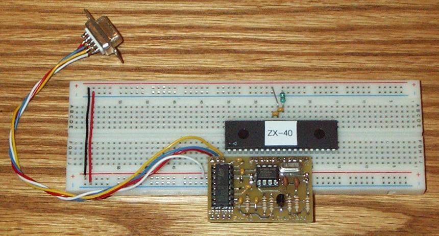
A prototype interface board for the ZX-40 has been created and is being tested. The board is designed to plug into a solderless breadboard, connecting directly to pins 5 to 15 of the ZX-40 and supplying nearly all of the connections required for ZX-40 operation. Pictures of the prototype can be viewed using the links below.
The first picture shows a complete setup ready for operation. All that is needed is a +5 supply. The interface board gets its power from the lower two bus bars on the solderless breadboard.
ZX-40 Interface Board #1
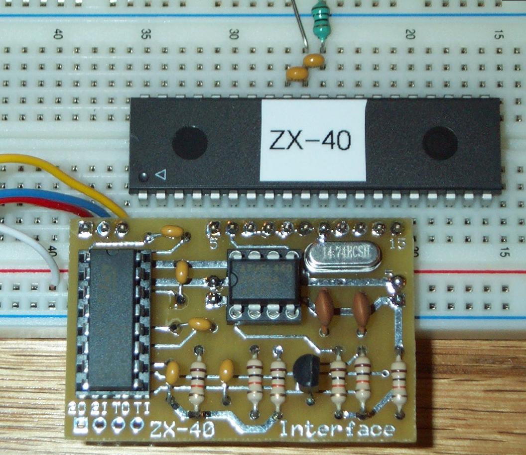
The second picture shows a closer view. Although it is difficult to see, there is a row of exposed connection holes between the interface board and the ZX-40 chip. In the lower lefthand corner you'll see the extra set of RS-232 level converter connections that could be used for one of the Com3-6 ports.
ZX-40 Interface Board #2
We have a few extra of the bare boards if you'd like to try one out. The board does not have solder mask or silk screen but is serviceable nonetheless.
ZX-40 Interface Board
ZX-40 Interface Board
- Don Kinzer
That is a neat little device. It sure improves the convenience of using ZX-40. (I bet it is also applicable to a bare ATMega32 as well!)
It also looks easy enough for a novice solderer to put together. It was my opinion that the major stumbling block in the use of the 40 (at least it would have been for me) was the need to have all the external support hardware. Now that it is all available on a single board, using the 40 is nearly as simple as using the 24!
Great idea.
-Tony
I think you are missing the whole point Tony. The ZX-40 (which I asked Don to produce) and ZX-44 provide additional flexibility and more I/O ports. If it is too inconvenient then stick with the ZX-24 (or when available the extended ZX-24 - see about128.html).
But for OEM applications or for people who like me who want the flexibility then the ZX-40 and ZX-44 are great. Don's board is good for newbies but most people will build their own interface board or custom circuitry. See also the Breadboarding Interface on my projects page which I created for the BX-35 and updated for the ZX-40.
Below is a picture of a ZX-40 based Robot Controller board that includes a ZX-40 and SPI EEPROM. The serial download is done via a header on the bottom right of the circuit board. This started out as a BX-35 controller board and I converted to a switchable BX-35/ZX-40 board by adding a jumper for ATN (either to PB1 or Reset). The crystal is also in a socket so it can be switched.
- Attachments
-
- ZX-40 Robot
- zxrobot.JPG (60.48 KiB) Viewed 14954 times
Mike Perks
The idea behind this board is to make it simpler to prototype an application based on the ZX-40. As Mike points out, if you were to take such an application to production, you would most likely incorporate the support circuitry on your board.It sure improves the convenience of using ZX-40. (I bet it is also applicable to a bare ATMega32 as well!)
...
Now that it is all available on a single board, using the 40 is nearly as simple as using the 24!
The interface board could be used with a PDIP-40 mega32. In that case it would be providing the serial level translation and the crystal. The EEPROM and ATN circuitry would be of no use, though.
- Don Kinzer
Don & Mike,
You are both right! Yes, as a project goes along, a dedicated circuit board with all the stuff you need and nothing extraneous will eventually be developed.
But for many of my projects, they never leave the breadboard! Therefore, having a nice sub-system on a PCB is a great time saver, and improves reliability if (like me) you send the robot out into the real world with (some) breadboarded stuff.
I have not used the "strip" board (vero board) but I have used the less convenient boards from radioshack. I only use them after I have a fairly mature breadboard, though.
So, it is my opinion that this neat PCB support board will be of use to everybody!! If someone is like me, they may find that despite being a relatively raw novice, you still need more than the I/O than the ZX-24 will give.
I am still gradually working out the kinks for my robot rover, including GPS long-range navigation, and ultrasonic short range navigation.
I even considered a blimp autonomous vehicle, but batteries would probably not give enough range, nor enough power to overcome even slight wind. I envisioned launching it from the flying field, then having it rise to a safe height and make a bee-line home, then land in the yard.....
Like a homing pigeon!
Right now I am trying to get the rover to home.
-Tony
Just to continue this thread a little further. I agree that the ZX-40 interface board is good.
Part of my "methodology" is to first draw up the schematic in EAGLE before even starting to breadboard. This design step lets me get my thoughts in order without having to worry about physical components and layout. After prototyping (and iterating) on the breadboard, I update the schematic and create an EAGLE board layout for veroboard. After a few more iterations its out with the drill to make strip breaks and the soldering iron.
If you are interested I have an detailed article on my website about the veroboard process I use.
After breadboarding I like to get my circuits onto something more permanent. This avoids problems like loose wires, inadvertent shorts and frees up the breadboard for the next circuit. I now have a second larger breadboard for "overflow" work. I love veroboard (stripboard) as it is less messy than chemicals and has a more friendly layout compared to other prototyping boards. Yes it does take a little work to transfer a circuit but the alternatives for one-offs are worse in my view.spamiam wrote:But for many of my projects, they never leave the breadboard! Therefore, having a nice sub-system on a PCB is a great time saver, and improves reliability if (like me) you send the robot out into the real world with (some) breadboarded stuff.
I have not used the "strip" board (vero board) but I have used the less convenient boards from radioshack. I only use them after I have a fairly mature breadboard, though.
Part of my "methodology" is to first draw up the schematic in EAGLE before even starting to breadboard. This design step lets me get my thoughts in order without having to worry about physical components and layout. After prototyping (and iterating) on the breadboard, I update the schematic and create an EAGLE board layout for veroboard. After a few more iterations its out with the drill to make strip breaks and the soldering iron.
If you are interested I have an detailed article on my website about the veroboard process I use.
Mike Perks
I read the article with great interest. I would like to get the veroboard. Where do you get it? I usually order stuff from DigiKey (I have an order building up right now! I also am known to use Jameco.mikep wrote:If you are interested I have an detailed article on my website about the veroboard process I use.
I suppose that I could make my "big" order from soemwhere else than Digikey to get the veroboard and minimize the shipping costs.
-Tony
As it says in the Breadboard Project my on site (http://home.austin.rr.com/perks/micros/Projects/), the best source I have found for buying stripboard in the USA is AllElectronics. The part number is ECS-4 and costs $5.50 for a stripboard that is 38 strips by 55 holes as shown in the picture below. They also sell single-sided perfboard, 2 or 3 hole pads and IC pattern boards with the same Euro size (6.3" x 3.94").
Mike Perks
Would this board also be useful for a "raw" ATmega32 PDIP device?
I would presume so, but the user would have to add the appropriate connections for ISP/JTAG separately.
It seems to me that this would be a useful and probably cost effective alternative to other development boards.
I ask this because I do not need a ZX-40 right now, but I could possibly foresee the need for an ATmega32. I did have the need for an ATMega128 developement board. It came with a bunch of bells and whistles that I do not need right now and cost about $100. A good deal for all the functionality it gives, but overkill for my
-Tony
I have a suggested enhancement to this interface board. I have just soldered up mine and it works fine.
The problem was with the J3/J4 2 pin headers for 5V and ground. One of my breadboards is labelled Red (which I use for +V) on the right hand side and the other is on the left. As it stands J3/J4 are connected the same and assume the +V is always on the left.
I suggest that for the next iteration, one of J3/J4 is reversed. Then when you build the board, you can solder in a header to either J3 or J4 (not both) depends on either your breadboard or personal preference.
Mike Perks